
Goal: Determine how a 2-meter 8-element Quad stacks up against the alternatives.
As you may recall, I recently added a 2-meter 8-element Cubex Quad to my ham shack. You can read all about it at Quad Antenna for 2 Meters. It’s been working well, but, as always, I’ve been trying to verify its operation and consider other options for meteor scatter and contest operations.
I inquired with Cubex Quads about their modeling and how they derived the gain figure of 14 dBi. The response was that since the new owner acquired the business, they hadn’t been able to locate any previous measures. That, by and large, left it to me to figure out. Here’s what I found and how I’m proceeding with the next station improvement.
EZNEC Antenna Modeling Software — K5ND Trial and Error
Quite some time ago, I’d investigated using EZNEC via a chapter in the ARRL Antenna Handbook and in the book Antenna Modeling for Beginners. After a few forays, I was not motivated enough actually to learn and use the software.
With the goal noted above, however, my motivation level increased. You can find the software at EZNEC.com. All the various versions are now free, including Pro/2+ v. 7.0. The creator W7EL is now retired. So, the software is readily available. Plus, there’s an excellent help file. He does not provide any support, which is to be expected after retirement. But you can also find information online.
My approach this time was to grab a sample and modify it for the exact measures. A great deal of trial and tons of error followed that. But I did finally manage to sort through most of the errors. At least, I hope so.
Modeling Quads and Yagis
I discovered that modeling a quad is much more involved than modeling a Yagi. The complexity comes into play when specifying each wire. For a quad, there are four wires in each element. Plus, those elements extend across the X, Y, and Z axes. For a Yagi, there are two wires in each element. They only extend across the X and Y axes.
Quad Modeling Outcome
First, I selected a 15-meter 3-element Quad sample file. Then, I modified it to match my measurements from the 2-meter 8-element Cubex Quad. I encountered a few snags from unfamiliarity with how the modeling wires were drawn. But after obtaining a ridiculous radiation pattern, followed by considerably more thought, I made the changes needed to produce what I believe is a reasonable representation of the pattern, gain, and front-to-back measures. You can see the antenna view and azimuth plot below.
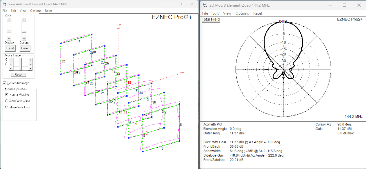
The measures on the Cubex Quad website show 14+ dBi gain and 25 dB front-to-back. My calculations from my inexpert use of EZNEC show 11.37 dBi gain and 35.6 dB front-to-back. The gain is roughly 3 dB lower than that claimed. Although, the front-to-back is much better. Note that this is the free space measure. It doesn’t attempt to model any ground effects.
Given this outcome, I was a bit disappointed. But I also wondered first about my ability to create a representative model and second about the modeling outcome itself. So, I modeled a few Yagi antennas that had published gain measurements.
Yagi Modeling Outcomes
Starting with Yagi modeling involved picking up a sample file for a 6-meter Yagi and then modifying it for the Yagis of interest.
I started with the Directive Systems DXEJX5-50. I have this 6-meter, 5-element Yagi on my push-up mast in the backyard. My modeling efforts yielded a 9.86 dBi gain versus the 10.1 in the datasheet. Front-to-back weighed in at 25.6 dB modeling versus 25 dB. The azimuth pattern looked identical.
Next, I modeled the Directive Systems DSE RS 6-EL 2-meter rover Yagi. I have that one in my garage ready for any future rover or portable operations. The modeling came in at 12.33 dBi gain versus the published 12.25 dBi. Front-to-back modeling showed 17 dB versus published 21 dB. This also revealed that the simple rover Yagi was marginally better than the quad.
All that seemed to say that the modeling was working, or at least I was using the same modeling as Directive Systems.
Modeling 2-Meter Antenna Alternatives
As mentioned above, my goal was to figure out the next steps for a 2-meter antenna. I thought mounting two quads side-by-side might be just the ticket for more gain in my meteor scatter efforts. The modeling demonstrated that even with the additional gain of 2 to 3 dB from the second antenna, it would still not match the performance of many longer Yagi antennas.
That was clearly pointed out from the spreadsheet I’d built of 2-meter Yagis running from 9 to 12 elements. All of them weighed in around 14 dBi gain. Of course, many of them also weighed in heavy and long for my current fiberglass push-up mast.
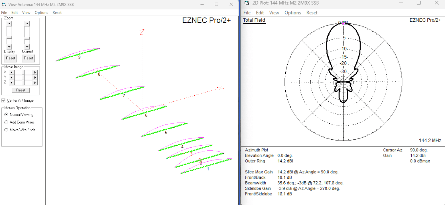
The one that makes the most sense for my backyard is the M2 2M9X 9-element Yagi. It’s roughly half the weight of the closest competitors with a 14.5’ boom length, the shortest of the lot. So, I entered it into the modeling software.
I’ve posted the antenna view and azimuth plot below. The model measured 14.2 dBi versus the published rating of 14.1. The front-to-back model shows 18.1 dB versus 20 dB. This shows another good match of published versus modeled measures.
Modeling in Free Space versus Ground
Not content to examine only the free space results, I started adding the ground to the model. The reason I started down this path was a thought that the published quad measures might be taking ground into account.
After quite a bit of trial and error, I did manage to look at ground effects on the two Directive Systems Yagis and the M2. It will take me some time, if I decide to invest the time, to add ground to the quad model.
This is because, for a Yagi, you only need to add the height above the ground in the Z axis. That’s straightforward since the wires for the elements do not require the use of the Z axis. The quad, however, uses all three axes to define the four wires of each element. Adding ground will require painstakingly adding the height information to every wire among the four wires that consist of eight segments in each element. That is 32 data points per element times six elements for a total of 192 data points. I’ll wait for motivation to arrive.
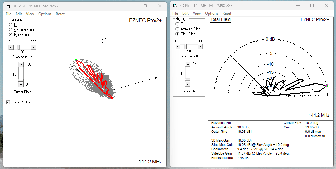
I’ve added below the results from the M2 2M9X 9-element Yagi. It shows the 3D pattern along with an elevation segment. It provides just a bit more insight into the antenna’s capabilities.
[Jump to the end of this article for my update on modeling the Quad against ground.]
What’s Next at K5ND?
I’m giving serious consideration to replacing the quad with the M2 2M9X. It’s pretty expensive compared to the other options. But the weight and boom length fit well. And I proved the radiation patterns are nice!
BTW. An adage I picked up during this investigation was to always look for the pattern plots before buying an antenna. If the antenna doesn’t have one, don’t buy one. I guess I learned my lesson. But I still had fun building and operating with the quad.
Good luck to you on your ham radio adventures. Thanks for reading about one of mine.
Update: November 2024
Dale Parfitt, W4OP, at Par Electronics, recently sent me a note on making a global change to antenna height in EZNEC. It was as simple as selecting WIRES, and in the popup window selecting WIRE and Change Height By…
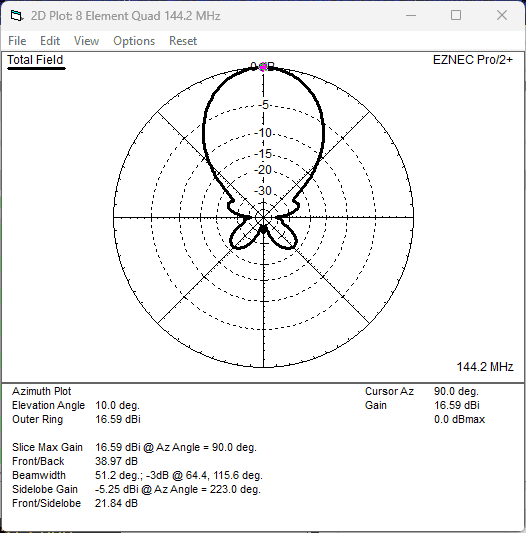
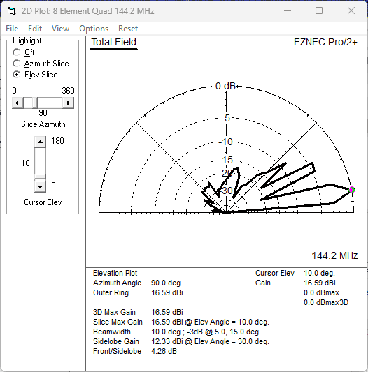
So, I found the 8-element Quad EZNEC description file, which was way more difficult than it needed to be due to my poor memory and challenged file system. Then I wrestled with EZNEC to find the right buttons to add 30 feet to the Quad height. Next I added Ground Type, followed by looking at the 2D and 3D plots. You can find the plots nearby.
I discovered that forward gain at 10 degrees came in at 16.59 dBi, versus the freespace 11.37 dBi. This is quite favorable compared to the published gain of 14+ dBi. This is still lower than the 9-element Yagi at 19 dBi. But the Quad’s shorter boom length and wide bandwidth make it very attractive for many applications.


[…] EZNEC antenna modeling Goal: Determine how a 2-meter 8-element Quad stacks up against the alternatives. K5ND […]
I’ve read from G0KSC site that any quad elements beyond 5 elements does not warrent the weight of quads .. so after the 5th element should just be yagi ….
Im still trying to model on my own computer … motivation is spotty since i work 3rd shift — always tired.
Hi Mike,
I expect that the G0KSC quads will get quite heavy. They are heavy-duty antennas with twin booms. The Cubex Quad is made from wire and fiberglass.
Here’s a quote on the G0KSC website: “Typically, the real and fundamental benefits are in outright performance. With a quad (below around 7/8 elements) you will see higher gain and better front to back ratio that a Yagi of any given Boom length. In most cases, higher gain can be produced with not just a shorter boom, with less elements too.” at https://www.g0ksc.co.uk/g0ksc-articles/owa-quad-intro.html
Here’s another, the one you’re referring to: “One of the big benefits of this antenna is the higher gain it can produce in smaller antennas when comparing against a Yagi. However, this benefit decreases with size as the longer the boom gets (and the more elements added) the less the associated gain advantage over a traditional Yagi antenna. By the time you get to 7 elements, the additional weight size and mechanical complexity starts to outweigh any performance advantage.” at https://www.g0ksc.co.uk/2013-yagis/all-quads.html
I see the 7-element LFA Quad weighs 9 lbs. https://www.innovantennas.com/en/shop-page/375/52/quad-beams/2m-lfa-q-quads/7-element-144mhz-lfa-q-super-gainer-quad-style-yagiInnovAntennas%20shop.html
The Cubex 8-element weighs 7 lbs. https://www.cubexquads.com/vhf-series/
Always tradeoffs. It’s fun to experiment.
Good luck.
Jim, K5ND
i wonder how the bandwidth compares between the 7-element LFA Quad and the Cubex 8-element …
My interest is kinda slanted twards a dual band beam …
Since i live in a semi-quiet area of idaho i think i can ignore front to back and focus on gain …
Thanks for reading more in one day than i do in a few nights — i do more research at work than i do at home but cant send anything to myself due to — well work.