I’ve been amazed by the relatively new Q65 mode within the WSJT-X software suite. It works over long distances when nothing else is happening. It’s said to operate via ionospheric scatter for terrestrial contacts and is becoming the go-to mode for moon bounce. This article provides a brief introduction along with current operating recommendations. The goal is to help you make QSOs when nothing else is working.
What is Q65?
Q65 uses a 65-tone frequency-shift keying modulation mode. It has a sync tone for both time and frequency synchronization. Q65 is particularly effective for tropospheric scatter, rain scatter, ionospheric scatter, TEP, and EME on VHF and higher bands, as well as other fast-fading signals.
Joe Taylor, K1JT, states: “Q65 will enable stations with a modest Yagi and 100 W or more to work one another on 6 meters at distances up to ~2000 km on most days of the year, in dead band conditions. Ionospheric scatter is best near mid-day and in summer months but is present at all times.”
That’s how it has worked for me. Moving to Q65 has made it happen from home or as a rover when nothing else is working. It, of course, helps to coordinate between the two stations, just as is done with meteor scatter contacts.
How Does Q65 Work?
With Q65, there are selectable transmit/receive sequences and sub-modes. For 6 meters, the general standard is 30-A, or 30-second t/r sequence and sub-mode A. For 2 meters, it’s 60-C, or 60-second t/r sequence and sub-mode C. The K1JT Quick Start Guide to Q65 recommends the following t/r sequences and sub-modes.
- Trans-Equatorial Propagation (TEP) on 50 MHz: 15C, 30C
- Ionospheric scatter on 50 MHz: 30A
- QRP ionospheric scatter on 50 MHz: 120E
- Ionospheric scatter on 144 MHz: 60C
- Troposcatter and rain scatter at 10 GHz: 60D
- Small-dish EME, 10 and 24 GHz: 120E
- Other EME: 50, 144 MHz 60A; 432 MHz 60B; 1296 MHz: 60C; 10 GHz: 60D
The sub-modes provide different tone spacings. The available t/r sequences are 15, 30, 60, 120, and 300 seconds. Here’s how those t/r sequences come into play with signal-to-noise ratios.
- 15 seconds, -22.2 dB SNR, with a priori (AP) decoding -23.7 dB SNR.
- 30 seconds, -24.8 dB SNR, with AP decoding -26.6 dB.
- 60 seconds, -27.6 dB SNR, with AP decoding -30.2 dB.
- 120 seconds, -30.8 dB SNR, with AP decoding -32.5 dB.
- 300 seconds, -33.8 dB SNR, with AP decoding -37.4 dB.
A priori or AP decodes messages using heuristics and available information, adding several dB to the SNR.
A big part of the magic of Q65 is that it averages the signals received. It keeps track of the sequences received and pieces the information together to achieve a decode. You can see this as the QSO develops. Decodes are tagged with “q” followed by one or two numbers. The first number shows the type of AP information used. The second number indicates the total number of received sequences averaged to produce the decode. Here are some examples.
- Q0 — This is a decode obtained without using any AP information.
- Q1 — This usually means that AP has decoded the message as a CQ call, with the DX Call and Grid unknown to AP.
- Q2 — This usually means that AP has used your call as AP knowledge but has assumed nothing about the DX Call or Grid.
- Q3 — This usually means that AP has used AP knowledge of your Call and the DX Call in the decode. It then looks for a grid, a report, 73, etc.
- Q32 — This means that a Q3 decode has been obtained after averaging 2 transmissions.
I found this information on KA1GT’s Basic Guide to Q65.
Q65 Operation and WSJT-X Settings
Here are the settings I’ve lifted from various websites and found helpful in my Q65 operations on 6 and 2 meters. The complete list of references is at the end of this article.
The standard operating frequencies that I’ve used are 50.275 MHz with Q65-30-A and 144.170 MHz with Q65-60C.
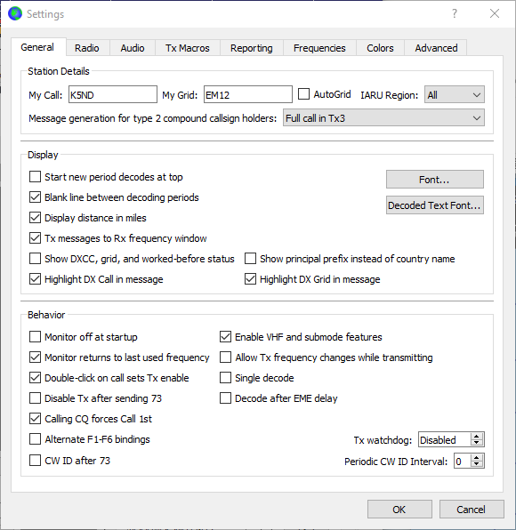
On the File/Settings screen shown above, remember to choose Enable VHF and submode features. Do NOT check Disable Tx after sending 73, since you may have to send it multiple times. It also is recommended that you do NOT check the Single Decode, although I’ve used it both ways for a successful Q65 contact.
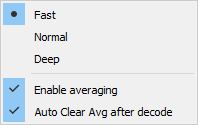 Under the Decode menu, select Fast, Enable Averaging, and Autoclear AVG after decoding.
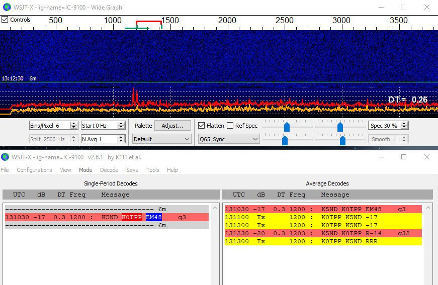
Selecting “Q65_Sync” on the Wide Graph will display an orange line with peaks that suggest potentially decodable Q65 signals in the most recently received sequence. When the accumulated average includes two or more reception intervals in the appropriate odd or even sequence, a red curve similarly shows potentially decodable signals.
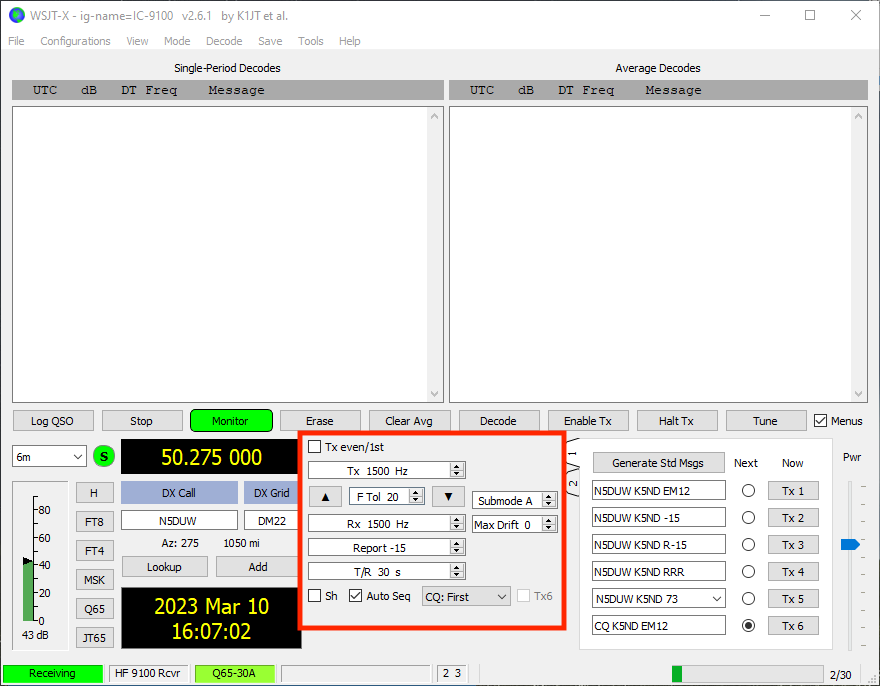
Set F Tol to 50 Hz or even 20 Hz for optimal decodes on a known audio frequency within the wide graph. In this image, the audio frequency is set to 1500 Hz. If you don’t know the frequency, you can set the F Tol wider to capture whatever’s there and decode it. Then you can zero in on the frequency.
If you’re working a schedule or coordinated QSO, not only will you enter the expected audio offset frequency, but you’ll also enter the DX call sign and grid before the start of the QSO. This helps the AP with its decoding tasks. It knows exactly what it’s seeking in the received signal and noise.
Select the T/R sequence. Here it is shown as 30 seconds. Select the sub-mode. Here it is shown as A. Leave the Max Drift at the default value of 0.
SH is not usually checked. This allows for sending single tones during a coordinated QSO. It’s mainly used at microwave frequencies.
Press Generate Std Msgs bar to fill in the messages to be transmitted. Check the Auto Sequence box. In a typical operation, you want to start with Tx1. However, with NA VHF contest mode, Tx1 starts calling with Tx2.
The setting here is 20 Hz F Tol, as shown with the green bar at the top of the wide graph. TX frequency is 1200 Hz. RX frequency is 1200 Hz. You can also see the orange curve showing the Q65 sync signal. Note, too, the sprinkles in the wide graph. Each decode is showing q3, indicating that the AP used both the DX Call and Your Call as entered and then looked for the signal report and messages.
This screenshot shows an initial q3 decode, and then a q32 decode. That last one required two averages to display the decode. I’m advised that the red line in the wide graph display represents the accumulated decodes over time and that the orange line represents the current decode. Let me know if I’ve got that wrong.
Q65 Averaging versus Period Length
As with most things, there are tradeoffs in the Q65 settings. Moving to longer t/r sequences will increase the sensitivity, as shown in the bullet list above. That should mean that fewer decodes are required before averaging is needed to help with the full decode. But shorter t/r sequences and more averages may help the QSO complete faster—something to consider when working with someone over very tough conditions.
I sincerely hope this has helped get you started with Q65. As usual, your mileage may vary. Consult the references for further background and detail. Good luck and have fun.
References:
https://wsjt.sourceforge.io/Q65_Quick_Start.pdf
http://www.bigskyspaces.com/w7gj/Q65SETUP.pdf
http://www.bobatkins.com/radio/Q65-averge%20_or_longer_period.html
http://www.bobatkins.com/radio/Q65_1296_setup.html
Q65 Update January 2024
The FCC has updated amateur radio regulations to allow 2.8 kHz bandwidth digital modes on the bands below 30 MHz. This means that MSK144 and Q65A can be operated on 10 meters and lower. I’m seeing that the current Q65 mode A calling frequency is 28.140 MHz.



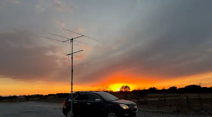


[…] WSJT-X and the Q65 mode for 6 meters and up It works over long distances when nothing else is happening. K5ND […]
[…] is small compared to the moon and geostationary orbit is a significant distance away, so they used the Q65 mode in WSJT-X which is specifically designed for recovering weak […]
[…] is small compared to the moon and geostationary orbit is a significant distance away, so they used the Q65 mode in WSJT-X which is specifically designed for recovering weak […]
[…] ist, und die geostationäre Umlaufbahn ist eine erhebliche Entfernung, sodass sie verwendet werden Der Q65-Modus in WSJT-X Dies ist speziell für die Wiederherstellung schwacher Signale […]
[…] is small compared to the moon and geostationary orbit is a significant distance away, so they used the Q65 mode in WSJT-X which is specifically designed for recovering weak […]
[…] is small compared to the moon and geostationary orbit is a significant distance away, so they used the Q65 mode in WSJT-X which is specifically designed for recovering weak […]