Some time ago, I implemented an Antennas-Amplifiers Preamp, Bandpass Filter, and TR Relay for 6-meters. It provides a separate output for a receiver, which allows direct connection of an SDR receiver. Also, since the transmit input is separate, it will enable the use of an attenuator that only affects the transmit power and not the received signal. This will allow me to protect the input of my TE System 6-meter amp, known to blow up from being overdriven.
Adding 2-Meters to the 6-Meter Setup
The system has been working since August 2021 and doing a great job on 6-meters. So I’ve now added their 2-meter version. I’ve also taken some time to pull together a bit of documentation that might provide insight to others and help me maintain the system better.
You can see the preamp unit in the photo above. It has a very sturdy package. You can also see my temporary use of a few cable adapters. I plan to update these with N connector cables soon. I’ve done that already for the 6-meter version, using N to UHF connector cables to eliminate the need for adapters. For 2-meters, I’ll mostly stick with N connectors throughout, as the Tokyo Hy-Power amplifier also uses N connectors.
[Update July 2024. I brought the 2-meter EME3 LNA to the Central States VHF Conference for testing. They measured a noise figure of 0.6 dB and a gain of 24.6 dB.]
DEMI LTRS Sequencer
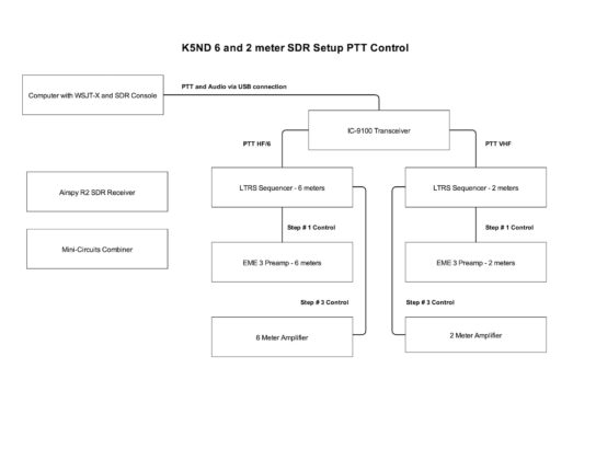
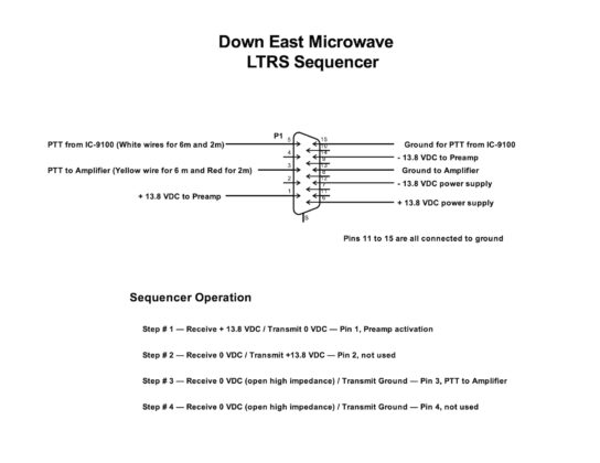
You can also see the Down East Microwave LTRS Sequencer in the photo. I have separate ones for 6-meters and 2-meters. It took me a bit of time for the first installation to figure out how best to connect things to prevent the preamp from getting toasted. One thing that puzzles me a bit is that the first unit I purchased has an LED that glows orange on receive and red on transmit. The second unit has an LED that glows green on receive, which matches the documentation. I’ll have to ask DEMI what’s up.
 Update October 2022 – I worked with DEMI, who provided Design Note 041, which isn’t on their website. They note that the transistor Q2 was changed and that required some changes. Primarily a rerouted 220-ohm resistor. That didn’t fix it. But a careful analysis of the new sequencer and the old sequencer revealed a wiring change that was needed. That made the fix, although there is a slight luminosity difference between the green side of the two LEDs. Here’s a scan of the DEMI LTRS Design Note 041. [In 2024, I bought another one. The LED brightness matches the 6 meter sequencer and it no longer bugs me!]
Mini-Circuits Combiner SDR Input
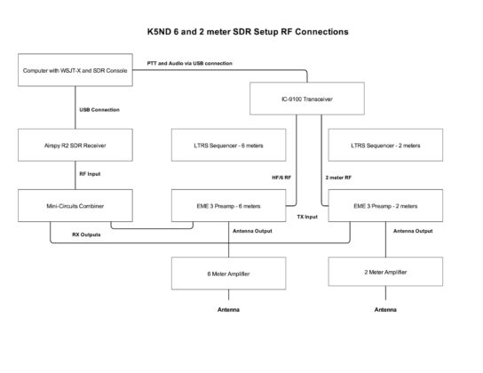
One challenge with the SDR is that it only runs one instance, so I need to switch between 6 and 2-meters manually. Rather than try some sort of manual switching on the input to the Airspy SDR running SDR-Console, I’ve used a Mini-Circuits Combiner/Splitter to route both 2-meter and 6-meter signals to the unit. The switching is then done on WSJT-X and SDR-Console.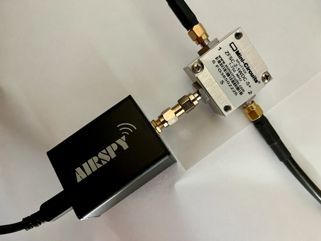
Documentation
I’ve used Digi-Key’s Scheme-it to draw diagrams of my setup. They are pretty simple and should remind me what I’ve wired and keep track of changes. They might also provide you with some thoughts on your setup. Click on the images for larger versions.
That’s what’s happening here. Next up — September VHF Contest.

